


![]()


![[ Polski ]](../../images/POLA001.gif)
![[ Deutsch ]](../../images/GERM001.gif) Describing multidimensional Vapor Diffusion
Describing multidimensional Vapor Diffusion
Computational description of vapor diffusion in building constructions can provide valuable hints for answering the questions if there is a risk of, potentially destructive, interstitial vapor condensation within the core if construction or not (Interstitial Condensation Assessment).
Diffusion equations have the same structure as those describing heat transfer and can be solved analytically only for one dimensional vapor diffusion. In all higher dimensional cases numerical methods, like the one implemented in AnTherm, have to be used.
![]() AnTherm calculates two- and three-dimensional distribution of vapor partial pressures in building constructions.
AnTherm calculates two- and three-dimensional distribution of vapor partial pressures in building constructions.
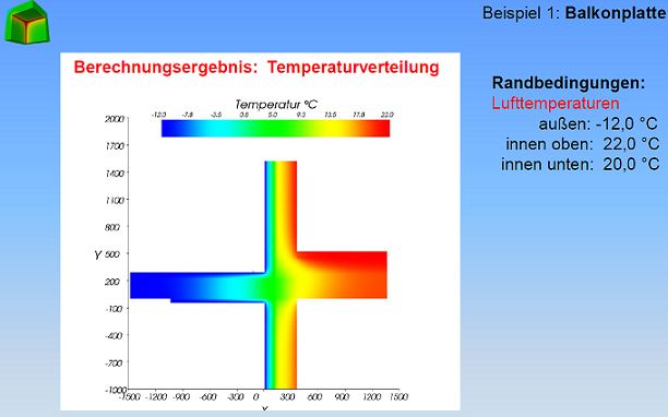
Saturation pressure distribution within the construction is computed too - based on the temperature distribution.
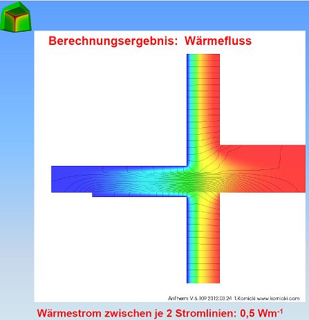
The comparison of the partial and saturation pressure distributions provides hint directly related to answering the questions if there is quantitative risk of condensation within the construction or not. All areas at which partial pressure of vapor is higher then the saturation pressure can be accounted as endangered and can be visualized as such graphically.
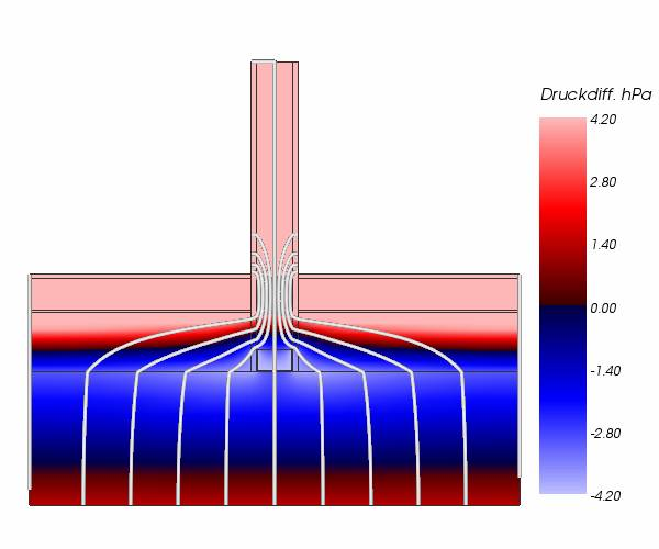 |
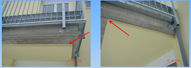
| This humidity model calculation shows, due to the cold bridge effect caused by a partition wall of stud framing gypsum plaster placed directly onto the slab on the one hand, and - due to the interruption of the moisture barrier on the war side, just below the heating pavement - the possibility of diffusing water vapor into the floor structure through the partition wall on the other, additional regions of higher condensation risk. These are highly distinctive in the surrounding of the bottom U-Profile of the partition wall. Legend:
|
 |
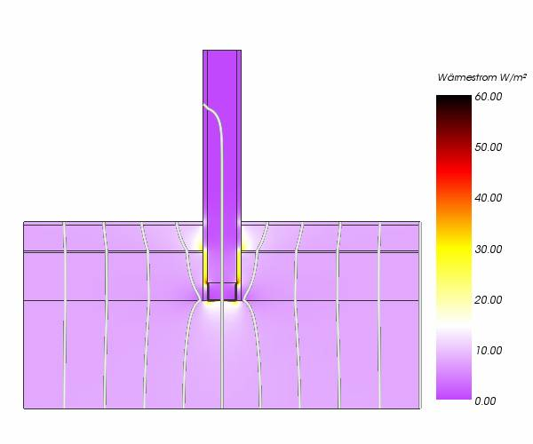
| Partition wall of stud framing gypsum plaster placed directly onto the 30cm thick concrete ceiling above basement garage, without thermal insulation on the cold side. The EPS heat insulation layer (Röfix 831, zementgebundene Polystyrolflocken) of 13,5 cm thickness has been placed solely on top of the concrete plaster - there is no other heat coating at the bottom side of the ceiling. The typical cross section of this ceiling construction has been assessed being not critical at all. Legend:
|
It has to be accounted, that when interpreting such results, diffusion is not the only driving factor for vapor transport. Especially within massive constructions water and vapor transport can be significantly influenced by capillary transport hence diffusion might be less significant then.
Transposing this method used in AnTherm onto the commonly used Glaser-Method for one dimensional case means, that intersections of vapor partial pressure distribution with saturation pressure distribution are calculated and regions within this intersections are interpreted as condensation risk areas. It is well known that the width of such zones is mostly overestimated.
The implementation provided in AnTherm shall be mainly used for answering the question if, and if so where within the construction, by given boundary conditions (air temperature and relative air humidity) moisture is produced. More exact estimation of condensation zones and moisture amounts is subject for future developments.
 |
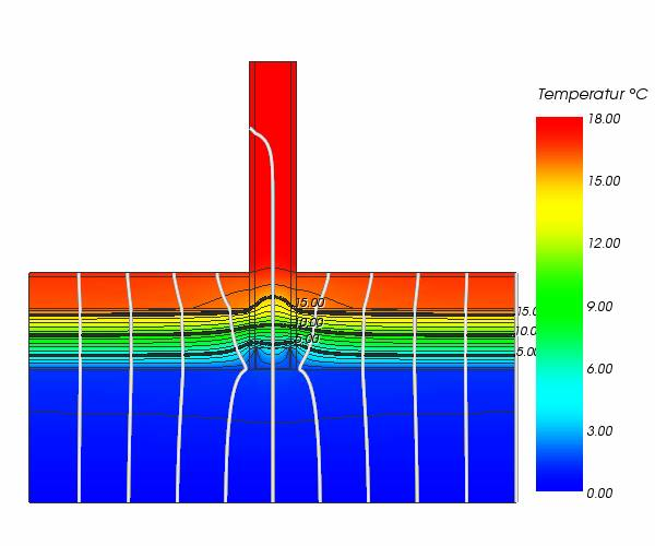
| This humidity model calculation shows, due to the cold bridge effect caused by a partition wall of stud framing gypsum plaster placed directly onto the slab on the one hand, and - due to the interruption of the moisture barrier on the war side, just below the heating pavement - the possibility of diffusing water vapor into the floor structure through the partition wall on the other, additional regions of higher condensation risk. These are highly distinctive in the surrounding of the bottom U-Profile of the partition wall. Legend:
|
 |
| Partition wall of stud framing gypsum plaster placed directly onto the 30cm thick concrete ceiling above basement garage, without thermal insulation on the cold side. The EPS heat insulation layer (Röfix 831, zementgebundene Polystyrolflocken) of 13,5 cm thickness has been placed solely on top of the concrete plaster - there is no other heat coating at the bottom side of the ceiling. The typical cross section of this ceiling construction has been assessed being not critical at all. Legend:
|
A heat bridge is an area where the heat flows significantly faster to the outside due to the temperature difference between the cold outer air and the warmer inner air. The decline of the surface temperature at the side oriented towards the space with colder outer air temperatures increases the risk for the formation of condensation water. That is why heat bridges not only concern heat insulation but also protection against moisture. Various kinds of damages may occur:
- Mould fungus
- Frost damage
- Corrosion
Interested?
Contact
us for more information.
Or try and evaluate the demonstrational version just now!